Steel box girder redesign in place of cast-in place concrete box
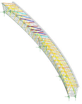
Linear static modelling using beam and shell elements
Significant cost savings made
Finley Engineering Group, Inc. (FINLEY) used LUSAS Bridge for its engineering redesign of the Estero Parkway Flyover in Fort Myers, Florida, for the contractor, ZEP Construction. In doing so, FINLEY four-steel box girder design produced significant savings in construction costs over an initially proposed cast-in-place concrete box girder design. As the result of the engineering redesign done using LUSAS and cost-effectiveness measures taken by Zep Construction, $1.85 million will be passed to the project owner, Lee County, Florida, as a value engineering credit.
Overview
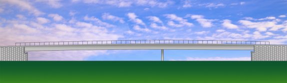
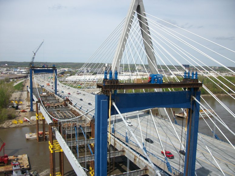
The Estero Parkway Flyover is 561 feet long, with spans of 340 and 221 feet, and approximately 116 feet wide. It will extend Estero Parkway over Interstate 75, connecting with Ben Hill Griffin Parkway, which then meets with Corkscrew Road to the southeast of the city.
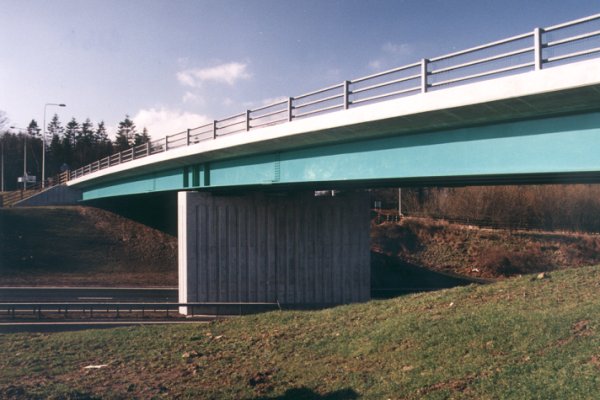
FINLEY redesign replaces proposed twin, cast-in-place concrete box girders with a single, four-steel box girder design. This solution provides significant savings with the elimination of a large falsework support system, reduced construction time, reduced foundation design requirements and simplified construction. By using shallower steel girders, shallower approach grades can be used, saving fill and construction time. It also means that the contractor can erect the bridge in longer sections meaning fewer obstructions in the roadway.
The new design uses a staged temporary tower support scheme to optimize the efficiency of the steel section which allowed the steel bridge solution to be more attractive against a cast-in-place concrete one. The redesign also enhances overall project safety with the elimination of the falsework system over the interstate and reduces the risks associated with a constrained traffic pattern through the falsework system.
Bridge Construction
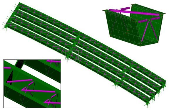
Each curved steel box girder comprises webs of 1″ thick plate and top and bottom flange thicknesses of 1-1/4″ plate. Internal X bracing formed of WT and L sections is used in conjunction with diagonal top flange bracing of WT sections to stiffen the girders. At supports, 1-1/4″ thick internal diaphragms with access holes are used with end diaphragms of 1/2″ thick web and flange plates connect adjacent girders.
Modelling and analysis
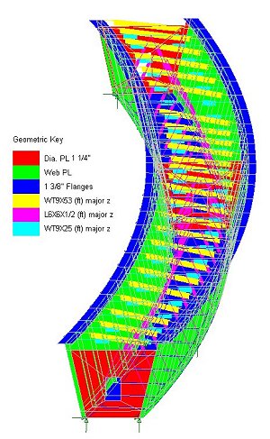
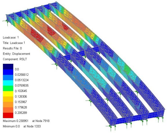
In all, 15,000 quadrilateral thick shell elements modeled the 4 box girders and stiffeners in the bridge structure. Customized displays of assigned geometric attributes such as steel plate sizes were produced by visualizing each thickness in turn – especially useful for checking that the correct thickness assignments were made. This in conjunction with the LUSAS groups facility, which permits easy definition and isolation of each sub-element of the model for display and model building purposes, and the fleshing facility, which helps ensure the correct orientation of standard section sizes is obtained, helped FINLEY to build the model in a very straightforward manner. Pinned supports including the temporary supports beneath the longest span were assigned to the model and a linear static analysis was carried out. From the LUSAS analysis overall girder displacements and stresses in the bracing struts and girder plates were obtained for the applied loading.
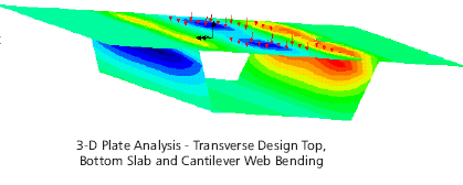
Resultant displacements from deck pour loading
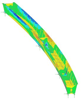
Typical absolute stresses in girder 1 from deck pour
Colour coded axial stresses in girder 1 bracing struts from deck pour
Benefits obtained
Craig Finley, president of FINLEY said: “We see this as a great example of what can happen with value engineering when the owner, contractor and engineer come together to create a design that takes the contractor strengths into account and that utilizes the best material and the most appropriate software for the challenges of the project.” He added: “In this case, the redesign from concrete to steel had an overall positive effect on the cost, schedule, and efficiency of the bridge, and the use of LUSAS helped us meet our design deadline and to prove an alternative bridge design that will ultimately save the client a great deal of money in construction costs.”
This view was echoed by Donald Deberry, P.E., public works operations manager for Lee County. “We are obviously pleased,” he said. “We always appreciate working with engineers and contractors who are willing to take a second look at projects and find ways to give the public more bang for their buck.”
“The use of LUSAS helped us meet our design deadline and to prove an alternative bridge design that will ultimately save the client a great deal of money in construction costs.”
Craig Finley, President, Finley Engineering Group Inc.
유사 사례
[Bridge] 워터게이트 교량해석(아일랜드)
[Bridge] Glen 교량과 Taney Road 교량 (아일랜드)
적분 교량 버팀대 설계
[Bridge] 장대레일 철도교의 해석 자동화 (한국)
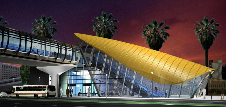
두바이 메트로 경량 철도 프로젝트를 위한 보행교의 해석 및 설계
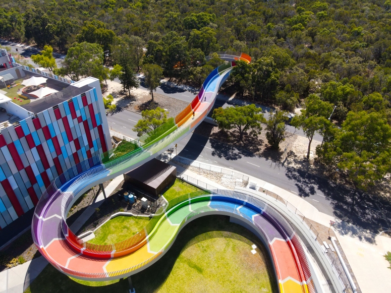
아이들의 교량
호남 고속철도에 대한 레일 트랙/구조 상호작용 해석
파세오 교량 해체
레드헤이즈 교량
[Bridge] Nesden 교량의 해석 (영국)
LPI 활용 기초 - 매크로 정의
LPI 란 ?
LUSAS Programmable Interfaace 를 의미하며, 반복적으로 수행하는 작업들에 대한 매크로를 정의하여 활용하는 것으로부터 LUSAS 를 플랫폼으로 하는 모델링, 해석, 설계검토, 도면작성 등의 전과정에 대한 자동화 프로그램 개발에도 활용할 수 있습니다.
작업 기록 개시
File > Script > Start Recording
대화창에서 파일명을 지정하면, 이후 작업들이 VBS 혹은 JS 명령문 형태로 저장됩니다.
Line 1 개 정의
모델러에서 Line 1개을 정의해 봅니다.
작업 기록 종료
File > Script > Stop Recording
기록을 종료합니다.
기록 내용 확인
아래와 같이 Line 을 정의하는 명령문 조합이 기록됩니다.
기록 내용 수정
아래와 같이 기록된 내용을 수정해 봅니다. 좌표를 변경시켜 가며, 총 10회 반복하도록 한 것입니다.