As part of Wichita riverfront development program, two cable-stayed pedestrian bridges are being constructed to extend the city cycle network and provide better access to the surrounding neighborhoods and business attractions. The bridges?contractor, Dondlinger & Sons Construction Co., Inc., retained Genesis Structures to analyze the staged erection process and prepare the erection manuals required for each of these complex cable-stayed bridge structures. Genesis Structures used LUSAS Bridge analysis software to carry-out numerous detailed 3D linear and nonlinear analyses of the bridges and their components to help minimize the number of steps in the cable tensioning process and reduce the Contractor’s time and labor.
Overview
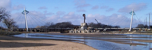
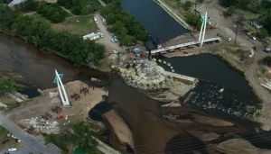
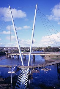
The city of Wichita, Kansas, boasts a bike and pedestrian transportation system that covers more than 150km, much of which runs through parks and along its rivers. As part of its riverfront corridor improvement project, two new bridges spanning 320m and 240m will cross over the Arkansas and Little Arkansas Rivers respectively at the site of the “Keeper of the Plains,” a 45m high, raised, iconic Indian statue. The bridges connect Exploration Place, a modern, interactive science museum, with the culturally significant Mid-America All indian Center. Because of their location, the cable-stayed bridges incorporate tapered towers and a unique stay-cable configuration that mimic feather shapes and other patterns found in Native American headwear.
Bridge construction
Each bridge is comprised of a 120m high steel tower of 60″ triangular cross-section that supports precast concrete box segments that are initially built on falsework bents and then longitudinally post-tensioned together.
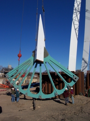
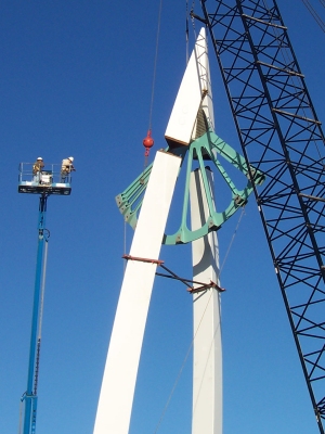
Each tower is formed from two, 60 ton steel leg segments that are lifted into position using a specially designed lifting saddle and integral lifting lug. A 30 ton upper cable anchorage unit sits on the top of both tower legs. This anchorage was assembled at ground level for ease of installation of the bolted connections and then raised atop the legs using special rigging. Adjustments were made using a screw jack system to obtain the correct tower leg positions prior to final assembly. Partial penetration welds around the full perimeter of the upper ends of each leg and the unit secure it in place.
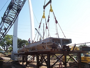
Decks are constructed of 32?long, hollow box segments having a maximum depth at the bridge centerline of 48″ and tapering to a 24″ visible profile. During assembly each segment is placed on steel falsework bents that allow longitudinal movement of the segments during placement and longitudinal post-tensioning. Ten inclined cable pairs support the longer span bridge deck and eight cable pairs support the shorter bridge. Main stay cables (provided by CBSI, Inc.) are 2″ diameter with back stay cables of 3 3/8″ diameter ASTM A586 Structural Strand.
Staged erection analysis
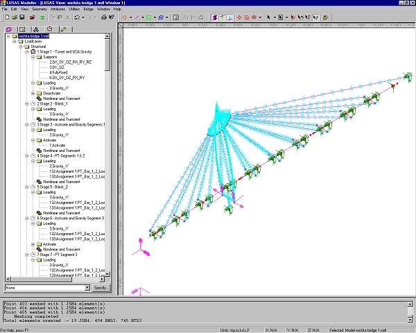
Analysis with LUSAS was required to model the complex erection sequence involving falsework construction in the river, post-tensioning of the precast concrete deck system, and sequential cable tensioning to lift the structure from its temporary supports to create the free-spanning cable-stayed spans.
Project specifications required that the bridge geometry be set-up at the beginning of its service life to obtain the target geometry after 10 years of service. To accomplish this, time-dependent effects due to creep and shrinkage in the post-tensioned concrete deck segments had to be evaluated. This was achieved by using the CEB-FIP 1990 creep and shrinkage material model in LUSAS.
After tower erection each of the 32m long deck box segments were constructed upon structural steel falsework bents and initially post-tensioned together for continuity using four, 1″ diameter post-tensioning bars. Following the complete longitudinal assembly of the segments, four 19 strand, 0.6″ diameter tendons were installed and tensioned to obtain the required compression in the deck system prior to cable installation. The LUSAS post-tensioning wizard was used to model the erection of the deck segments at each stage of the construction.
Preliminary tensioning of the stay cables in the LUSAS model was accomplished through initial strain loading of the nonlinear beam elements representing each cable. During the actual stay-cable installation, the longitudinal concrete deck system was to be lifted from its temporary supports through a carefully planned installation sequence. The falsework system was required to allow longitudinal movement and shortening of the deck system as well as unrestrained lift-off from the supports. Modeling for these effects was accomplished through the use of nonlinear joint element supports in LUSAS. Final tensioning of the stay cables was achieved by applying a negative temperature load to each cable pair to obtain the desire tension. Excellent correlation was obtained between LUSAS predicted cable tension values and on-site measurements.
3D solid modelling of box segments
Each of the box segments contained access openings in the top slab to provide access for the installation of the longitudinal post-tensioning system as well as for two tuned mass dampers (provided by Motioneering, Inc.) to control pedestrian-induced vibrations. Openings for the tuned mass dampers exceeded 15?in length and created areas of discontinuity in the top slab during lifting operations and longitudinal post-tensioning. To verify that each of these locations provided adequate continuity, individual segments were modelled using 3D solid elements and checked for both lifting stresses and longitudinal stresses due to post-tensioning.
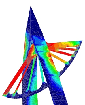
3D modelling of tower
The unique tower design of these bridges creates a highly confined compression and flexural zone immediately below the upper cable anchorage. To ensure adequate stress transfer brought on by the cable tensioning, a 3D LUSAS model of the entire tower and upper cable support was developed to determine the local zone effects in this region. Confirmation of the local stresses was obtained prior to proceeding with the complete analysis.
“We used LUSAS Bridge exclusively for the erection engineering of the Wichita Bridges and obtained excellent correlation between the on-site cable stayed measurements and the values that LUSAS predicted for lift-off”